Call us 24/7+86 18508516368

Pressductor Pillowblock Load Cells Vertical Measuring PFCL201CE-50kN 3BSE006699D0005

Load Cells PFCL201CE-50kN 3BSE006699D0005

The load cells are installed under the roll bearings, where they measure forces at right angles to the mounting surface.

The reactive force from the strip, which is proportional to the strip tension, is transferred to the load cells via the roll and the bearings.

The load cells are connected to the control unit via a junction box. The control unit converts the load cell signals to DC voltages that are proportional to the reaction force. Depending on which control unit is chosen, it is possible to have the analog signals for the two individual load cells (A and B), the sum of the load cell signals (A+B), and/or the difference between the load cell signals (A-B).

Principle of Measurement

The load cell only measures force in the direction FR. The measurement force may be positive or negative. The load cell is normally installed under the roll bearings. When there is a strip in tension over the roll, the tension (T) gives rise to two force components, one in the direction of measurement of the load cell (FR) and one at right angles (FV).

The measuring force depends on the relationship between the tension (T) and the wrap angle formed by the strip around the measuring roll.

General

The load cell is machined from a single piece of stainless steel. The sensors are machined directly in the piece of steel and are positioned so that they are sensitive to force in the direction of measurement and insensitive in other directions.

The load cell is mounted on a base with four screws, and the bearing housing is mounted on top of the load cell with four screws.

Every load cell comes calibrated and temperature compensated.

The load cells PFCL 201C/201CE/201CD are available in four measurement ranges, all variants have the same external dimensions.

The load cell PFCL 201C is equipped with a connector for the pluggable connection cable.

The load cell PFCL 201CE has a fiWed connection cable with protective hose.

The load cell PFCL 201CD is provided with an acid-proof cable gland with a fiWed PTFE- insulated connection cable.

Accuracy and Accuracy Class

Accuracy class is defined as the maximum deviation, and is expressed as a percentage of the sensitivity at nominal load. This includes linearity deviation, hysteresis and repeatability error.

Linearity Deviation

Linearity deviation is the maximum deviation from a straight line drawn between the output values at zero load and nominal load. Linearity deviation is related to the sensitivity.

Hysteresis

Hysteresis is the maximum difference in the output signal at the same load during a cycle from zero load to nominal load and back to zero load, related to the sensitivity at nominal load. The hysteresis of a Pressductor transducer is proportional to the load cycle.

Repeatability error

Repeatability error is defined as the maximum deviation between repeated readings under identical

conditions. It is expressed as a percentage of the sensitivity at nominal load.

Compensated temperature range

The temperature drifts of the load cell have been compensated for in certain temperature ranges. That is the temperature range within which the specHfied permitted temperature drifts (i.e. zero point and sensitivity drifts) of the load cell are maintained.

Working temperature range

Working temperature range is the temperature range within which the load cell can operate within a specHfied accuracy. The maximum permitted temperature drifts (i.e. zero point and sensitivity drifts) of the load cell are not necessarily maintained in the whole working temperature range.

Storage temperature range

Storage temperature range is the temperature range within which the load cell can be stored.

Zero point drift with temperature

Zero point drift is defined as the signal change with temperature, related to the sensitivity, when there is zero load on the load cell.

Sensitivity drift with temperature

Sensitivity drift is defined as the signal change with temperature at nominal load, related to the sensitivity, excluding the zero point drift.

Compression

Compression is the total reduction in the height of the load cell when the load is increased from zero to the nominal value.
Related recommendations:
Schneider Automation 140XTS00200 
Honeywell 900TEK-0001
WAGO 750-602
KJ2201X1-BA1 12P3162X212 SLS1508
GE IC693ALG392C
80026-173-23-R
SPA-ZC 400
1785-L80B PLC-5
IRB6620 3HAC026114-001 RV
IRB 6603 HAC 022279-001002003007
2098-DSD-005X
ABB 3HAC029034-00
more……

Pressductor PillowBlock Load Cells PFCL201

These units are designed for strip tension measurement in applications where it is essential or advantageous to determine the vertical force component.

Machined from a single block of stainless steel, they have exceptionally high tolerance for overloads, shock and impact, in addition to high immunity to dust and corrosion.

The standard construction is of high resistant stainless steel with potted internal components. Mill-duty versions are available for exceptionally hostile environments in i.e. galvanizing or pickling lines.

Pressductor® Technology

The first Pressductor transducer was developed in Västerås, Sweden, in the early 1950’s and patented in 1954.

ABB’s well-known Pressductor® Technology is a measurement principle based on the magnetoelastic effect – the magnetic properties of a material are influenced by the mechanical force applied to it.

When exposed to mechanical force, ABB’s Pressductor transducer produces measurement signals as a result of changes in magnetic fields. (Move your mouse over the illustration to see these changes.) Because these signals are not contingent upon physical movement or deformation, the load cells combine sensitivity with extraordinary tolerance to overloads and virtually no built-in limit to the number of load cycles.

The ABB Pressductor transducers produces high-power, low-impedance AC signals that are very resistant to electrical interference and earth faults.

ABB’s Pressductor transducer stands for unbeatable load cell performance, thanks to its unique combination of accuracy, overload capacity and ability to withstand harsh environments. By using this technology you will achieve higher quality and reliability, especially under demanding conditions.
Related recommendations:
PD D405 A101  3BHE041626R0101
YPQ101E YT204001-FS
YPP109A YT204001-DL
PP5302B 3ADT306400R1
3BHB020720R0002 5SHY3545L0016
CP630-WEB 1SAP530200R0001
3BHE032025R0101 PCD235 A101
SD821 3BSC610037R1
3BHE024642R0101 GC D207 B101
more……

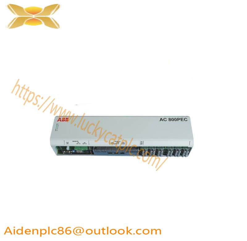
Versatile and reliable – the AC 800PEC PVD164A2059 3BHE014340R2059 adapts to any application 

Seamless integration into plant control

In today’s demanding market, a controller must not only deliver maximum performance but also provide transparency. In this respect, the AC 800PEC provides a large range of possibilities. Integrated communication ensures transparent, plant-wide data exchange and control – from overall plant control down to separate processes.ABB PP D113 PPD113 3BHE023784R2630 B01-26-111000 Modbus RTU - Advanced Industrial Automation Solution

Use of ABB’s System 800xA with the powerful AC 800PEC controller permits uniform automation throughout the plant, seamlessly integrating advanced solutions into the process control system. Strict security procedures and effective firewalls prohibit unauthorized intrusions and ensure permanent system safety.

The AC 800PEC provides connectivity, using either native (built-in) or add-on functionality.

Native (depending on the configuration):

− MMS

− Modbus TCP Slave

− IEC61850

− ABB Powerlink

− ABB Drivebus (DDCS)

− Iba-PDA

− Optical Modulebus (S800)

− CANopen

Add-on:

− Using ABB CEX Modules:

− ABB Drivebus (DDCS)

− Profibus Master DPV1

− Modbus RTU

− S100 I/O

− Masterbus 300

Using Anybus modules:

− CANopen

− ControlNet

− DeviceNet

− Profibus Slave

− Profibus Slave DPV1

− Profibus Master DPV1

− Profinet I/O

− EtherCAT Slave

− Ethernet/IP

Well suited to a harsh environment – the AC 800PEC for traction

Traction with its particularly harsh environmental conditions is one of the most important applications of the AC 800PEC. The controller operates through a wide temperature range (– 40 to + 70 °C), with vibrations according to traction standards. The compact solution is the ideal response to the demands of restricted spaces and allows integration of the processing unit together with all the I/Os in the same compact hardware device.

Top reliability is a must – the AC 800PEC in power generation

Typically, excitation systems are used for generator control in power-plants where high reliability is the No. 1 requirement. Due to the very short process cycles, traditional redundancy concepts are no longer applicable.

The modular architecture of the AC 800PEC not only greatly reduces the complexity of the overall system, but thanks to redundant subsystems also provides increased reliability. In the case of a problem in one subsystem, the main controller switches over to the remaining subsystems, which are scaled in such a way that the overall task can still be fulfilled. Should the main controller fail, a second controller is available in hot-standby.

Precision for optimum quality – the AC 800PEC for industrial processes

The most demanding function in a rolling mill is thickness control. By using the powerful AC 800PEC controller and its ability to implement C-Code beside the standard IEC 61131-3 program level, a new thickness control solution for cold rolling mills has been developed based on an MIMO (MultiInput Multi-Output) control concept. The benefit to the customer is an improvement in thickness deviation by up to 50 percent.

What you simulate is what you implement Straightforward engineering workflow

In the traditional development process, system engineers would define the specifications, which software engineers would then interpret – a time-consuming and error-prone process that also reduced the likelihood that the resultant software would correspond to the original specifications and concept.

The AC 800PEC development workflow uses MathWorks® tools for model-based design as a single development platform for the entire development process.

Simulink® is used to run system simulations. Real-Time Workshop® then automatically generates and downloads controller code from the Simulink® models to the AC 800PEC controller, eliminating the need to translate the models manually into C-code.The use of Real-Time Workshop® allows interactive debugging of the software on the controller. Specification and code are synchronized throughout the development process by using Simulink® models as executable specifications. Parameters can be changed and optimized on the PC, and code can be generated automatically from the models and then transferred to the controller directly via an Ethernet connection.
Related recommendations:
3BHE020570R1022 PPD114 B1022
3BHE014135R0011 UAD149 A00-0-11
PP D113  3BHE023784R2030
AC 800PEC 3BHE025541R0101
AC800F PM803F Base
HF HF2211A
3BHE023784R1023
PP D113 PPD113 3BHE023784R2630 B01-26-111000
PPD113 3BHE023584R2634
3BHE020570R1022 PPD114 B1022
3BHE020455R0001 PPD103 B01
PPD113B03 – 3BHE023584R2365
3BHE041576R3011 PPD517 A3011
PPD113B01 3BHE023784R1010
PPD114B1022 – 3BHE020570R1022
PPD104 3BHE017400R0101
more……

Search for products

Back to Top
Product has been added to your cart